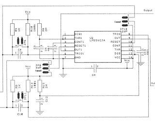
The Timing Section
The timing section is responsible for the pulse widths output as well as protection from both outputs being on that the same time.
The jumpers JP8 & JP10 in the first half are responsible for either treating the controls & outputs individually or as pairs. If they are both in the pins 1-2 RST position, everything is treated as paired inputs and the Reset inputs on the 556 timers are connected to the other input before pulse shaping. That means that zero or one side of the timer can be active at the same time. If the jumpers are both in Pin 2-3 positions, the halfs are isolated from head other and can be operated independently. This is useful if you want to control something else other then relays, such as lights or motors.
The timing is handled by R8+C3 and R15+C12. Usually both sides have the same values. If the pulse-shaper is in use, this controls how long the output will be on. If the shaping has been disabled and output follows input, this controls the switch debouncing to smooth the output. For relay/snap type switches, values of 2M ohm andd 0.10uF work very well to drive the relays for 2/10ths of a second. Changing the capacitors to 10uF makes a handy 20 second timer for tortoise switches to make sure they have made at all the way to the other side even if only a pulse was received on the input. The last thing you want is a switch halfway between positions!
For debounce only, the timing can easily be reduced by changing the resistors to lower values, even going as low as 100k-200k to get 1/100th - 2/100th's of a second debounce to reduce the obvious lag when the switch is turned off.
Capacitors C5 and C13 are optional and simply help make sure the timing stays more consistent. C9 simply helps get rid of power noise and in most cases isn't needed either, but a good practice to put in.
Since U2 is a 556 timer, that is a limiting factor on the lowe voltage power. 16V is it's max rating, which means the input and timing stages should normally be powered by 5V to 15V DC. It it important not to go over 16V! That's why I will repeat myself again later and mention that you can cut two runs to isolation the output power from this section and supply different power to both or install a 7812/7815voltage regulator and diode between the two!
Even when running in output follows input mode, it's recommended to use the 556 timers since even switch bounce. But when in that mode, you can drop the timing to a much smaller value by reducing the resistors. When pulse shaping is being used, you must ensure that the timing will make sure the switch travels to the other side!
Optional, easily bypassed
If timing isn't needed, we can easily bypass this by not installing the 556 timers and pulse shaping components, jumpering around the pule shaper, and then jumpering the 556 input to output. This turns the curcuit into on inverter, meaning that a low signal into the opto-couplers turns on the output stage, but is useful as a voltage or current converter.
I would encourage leaving the timer section in unless the inversion is required just for the sake of gaining the debounce capability of the timer.
Timing Schematic
The timing stage of half the circuit is shown below. A complete schematic will follow at the end as well.

No comments:
Post a Comment